Some risks are hard to ignore. The sound of a spinning turbine or snapping air breaker grabs your attention – it’s obvious that a failure could be catastrophic, and risk evaluation and mitigation follows somewhat instinctively. Earthing systems however, passive and innocuous, are often buried beneath the surface and hardly seem threatening. When earthing systems ‘operate’, they are unremarkable and are typically unnoticed. But when they fail to operate correctly, the results can be devastating.
What are the risks?
Power system earthing exists to provide three main functions: (1) keep people safe, including staff and the public; (2) protect equipment against damage, which can be costly, but secondary consequences can also be of significance to people; and (3) maintain system operations, which relies on adequate earthing to perform normal functions, particularly during adverse events.
The most prominent risk to safety is the exposure to voltages that would cause harm – most notably, current flowing through the heart leading to ventricular fibrillation.
But how does poor earthing lead to dangerous voltages? Isn’t earth safe by definition? When current flows through the earth and earthing systems (which occurs during both normal and fault conditions) voltages are produced on earthed components.
If the earthing system is appropriately designed and operating effectively, these voltages should be sufficiently low to present negligible risk.
However, changes in the condition of the earthing, such as deterioration or inadvertent modifications, can result in increases in voltage and/or exposure, and unacceptable risk.
And faults or changes in the earthing system can sit undetected – the first noticeable sign might be an electric shock! There are a range of criteria and approaches to help determine whether faults and changes are appropriately detected and that the risk is appropriately managed.
To read on this further, refer to Australian Standard AS2067:2016, or for a more detailed explanation, the ENA Earthing Guide EG-0 or the CIGRE Technical Brochure TB-749.Effective earthing is often also critical to protect equipment from excessive voltage or current.
Equipment failure can significantly interrupt network function, but can also be explosive or lead to the transfer of voltage hazards. When earthing systems fail to work appropriately, other parts of the system can also fail to operate correctly.
For example, if earthing is ineffective, a circuit breaker may not detect or properly clear a short circuit on a cable or powerline. Such failures, or maloperations, can create significant disruption, cost and safety risk, but can also be difficult to find root causes for, particularly where the cause is related to earthing systems or lightning protection systems.
Both good design and good testing are required
A well-designed system manages all of these risks, to a level legally and socially required, or to a lower risk if required by the asset owner or operator. But good design is only a first step toward acceptable risk.
Testing to verify the installation and validate the design, and then testing to detect change has become increasingly common and has more recently become clearly required of asset owners and operators (see AS2067 §9, §8.6; Appendix H also gives guidance on inspection and testing methods commonly used).
With all risks, but particularly those where latent or undetected faults may exist, the absence of evidence is not the same as the evidence of absence. If you want to be confident that your earthing systems represent an appropriate and acceptable risk, then you need to collect the evidence.
Condition (or state) assessments include visual inspection and continuity testing – demonstrating the effective bonding (or appropriate separation) of items to the earthing system.
Continuity testing does not directly measure condition, but provides patterns of resistances from one reference point, which can aid the tester in the identification of issues such as broken (or stolen!) bonds, deteriorated buried conductors, or loose connections.
This testing can be carried out on live assets, without the need for power disruption. Results can also be trended over time, giving a supplemental indicator of condition.
The principal test for performance is the low-current, off-frequency injection test, pioneered by Safearth, which simulates a single line to ground fault, often using the powerline or cable itself, and measures the resulting hazards and other impacts.

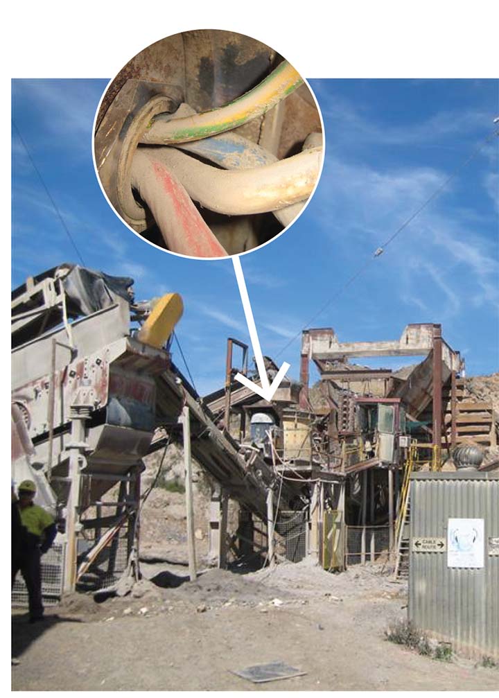
Incorrect earthing led to protection being unable to operate when a cable shorted to ground at Cudal Quarry, resulting in a fatal electric shock.
Once the test circuit and source current are established, a tunable voltmeter can directly measure touch voltages, step voltages and other transfer voltages, as well as voltages impressed on other systems such as pipelines or telecommunications systems.
This test method provides hazard and risk determinations with much lower error than could be achieved using numerical software modelling tools.
The distribution of the test current can also be measured, using an open-ended current transformer called a Rogowski coil. It can be wrapped around a pipe, shield wire, low voltage neutral or any other conductor to directly measure the proportion of test current flowing through each of the available paths.
Measurement with an appropriate instrument allows for vector current measurement, including both magnitude and phase, providing much greater accuracy.
This testing utilises specialised instruments that can allow measurement of the test signals without being swamped by the electrical noise of an operating power system. This enables testing to be carried out on and around in-service assets.
Testing and analysis can often be quite technical, but it is difficult to manage these systems without a detailed technical understanding.
Safearth, as Australia’s leading earthing and lightning protection specialists and pioneers in testing methodology and equipment, are well- equipped to provide training and assistance.
This Sponsored Editorial was brought to you by Safearth. For more information, click here.


